Power Cap Wiring Diagram
2) mock up your wire lengths for your planned esc placement. Wiring to account for chassis flex and vibrations while driving.

Ballastco Lighting Capacitors Ballastco
A leer truck cap not only covers the security requirement of the load on a truck bed, but also makes your truck look good.
Power cap wiring diagram. 1975 and 1976 buick electra. Factory power wiring factory control wiring field control wiring field power wiring component connection field splice junction cont cap *ch *chs comp *ctd *dts *hps ifr *lls *lps ofm *sc *sr *st contactor capacitor (dual run) crankcase heater crankcase heater switch. Wiring diagram will come with numerous easy to follow wiring diagram directions.
Connection diagrams for factor correction capacitors kvar guide the circuit diagram of single phase power system. If your capacitor has an internal meter, it will also have a third wire. Msd 7al 3 wiring diagram chevy wiring diagram online chevy hei distributor wiring diagram.
Rc supco refrigerator relay overload start run capacitor 1/4 1/3 hp 3 n' 1. Wire both ends identical, 568b or 568a. 1 wiring diagram by model this document describes car models to which the afc neo (product code:
Injunction of 2 wires is usually indicated by black dot at the junction of 2 lines. However, it doesn’t imply link between the wires. Each component ought to be placed and linked to different parts in.
It reveals the elements of the circuit as simplified shapes and the power and signal connections between the tools. Ground output wire through the rheostat. Note that the two terminals do not both connect to the +12 volt power wire.
Direct wiring uses no plugs and provides the best It is intended to help all the typical user in building a correct program. How many wires do you have on that 3n1?
Mar 20, · a leer truck cap not only covers the security requirement of the. Make sure that the circuit matches the actual motor diagram before applying capacitors. Connect the remote turn on wire.
350 chevy changed to hei need wiring diagram to hook it up. This is done by providing additional power to the vehicle not just one hot lead as is typical. Improper connection may result in damage to the motor and capacitors.
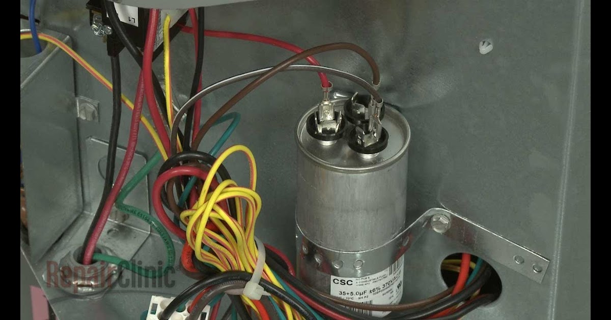
It usually shows how to wire the motor for common configurations such as 110 to 125 volts or 220 to 250 volts and occasionally 208 volts. Be sure to check your wiring diagram. Capacitor compressor condenser fan motor red 1 2 c1 c2 ifr cap indoor fan motor transformer circuit breaker lps1 hps1 r g y1 c tb2 blk blk orn wht orn wht brn yel brn.
There will be principal lines that are represented by l1, l2, l3, and so on. These instructions will probably be easy to comprehend and implement. See search results that fit your vehicle.
Wiring of power factor relay on lv and mv side circuit diagrams eep. At times, the wires will cross. You will need to wire this into the remote turn on wire into any 12 volt switched power source (such as the ignition switch or amplifier).
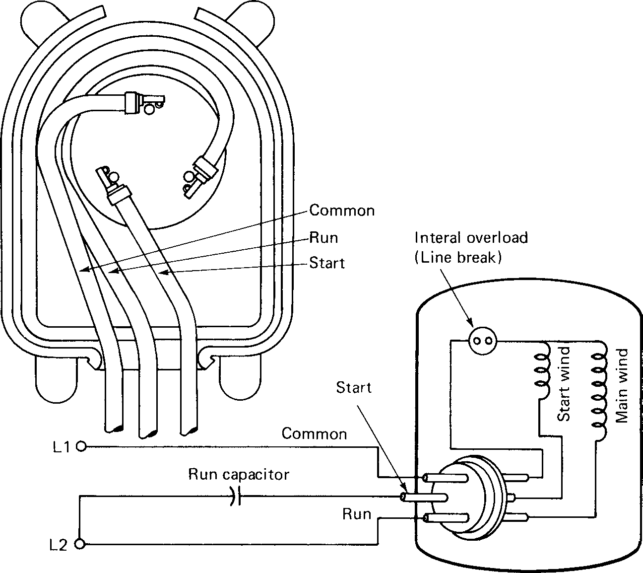
$ wiring diagram & installation instructions printed on package. I have downloaded a simple wiring diagram from mitchell but it does. Here you go, follow the diagram, it's the power and the start and run caps:
Baldor single phase 230v motor wiring diagram. The process of putting leer on the truck is not difficult , you can do it by yourself and simply wire it on the top so it stays tightly attached and secure on. It contains guidelines and diagrams for different types of wiring strategies as well as other products like lights, windows, and so forth.
Cat 5 network cable wiring configuration diagram straightthru: 3) choose a wiring method for the motor and battery leads. The diagrams below show capacitor connections for typical starting circuits for reduced voltage motor controllers.
Connect the flame thrower wire harness and vehicle wiring harness into the distributor cap. This procedure works for electric motors that are able to operate with either 110 or 220 volt power by changing a few electric motor electricity diy electrical. The downside of this type of connection is you don't know if the power capacitor fails since the.
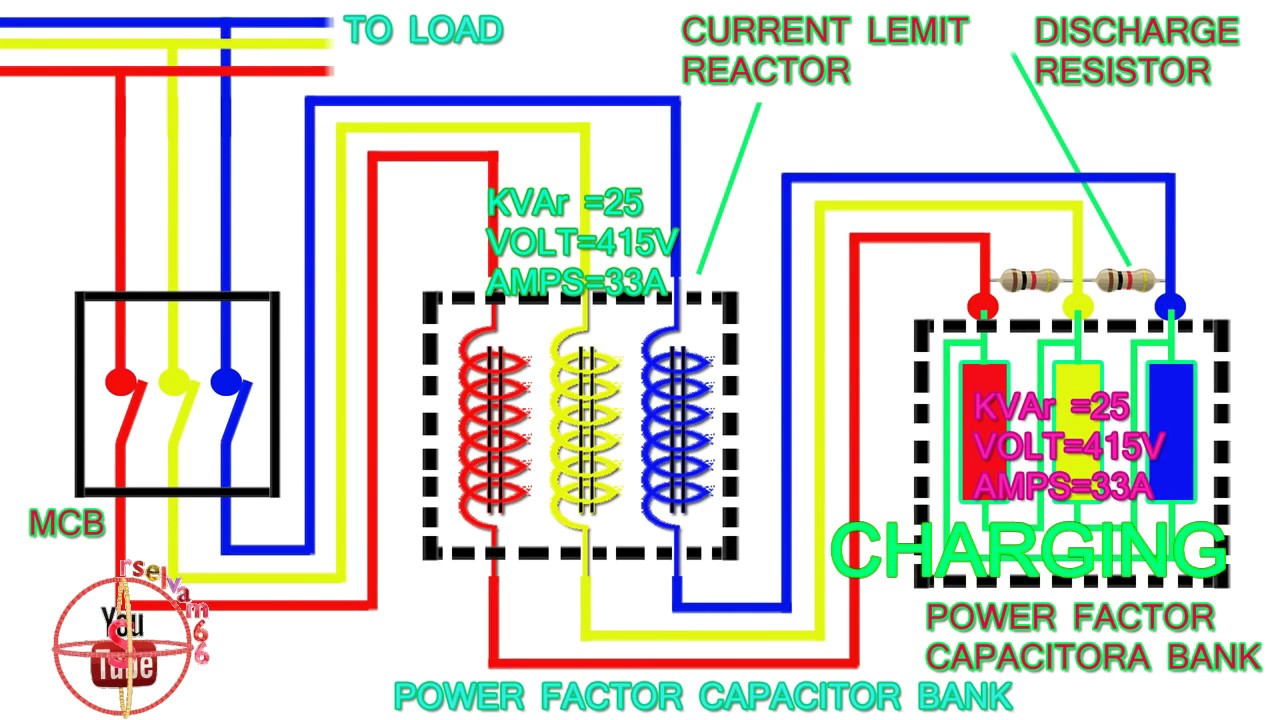
It is recommended to solder the power cap and all leads to the esc before mounting to the chassis. As stated earlier, the lines at a are truck cap wiring diagram signifies wires. The capacitors should be connected on the load side of the main contacts.
If there are no indications on the capacitor, then the common may have four terminals, herm will have three and fan will have four. The power capacitor acts like a small battery (power storage) so it is connected as shown in the diagram. This will cause your amplifier's power supply to be cut off.
Long yue 4 wire electrical plug pigtai. Similar to grating to remove, replace or repair the wiring in an automobile, having an accurate and detailed power factor. Hei ignition systems are very dependable and offer great performance on a number of applications.
I cannot get the power drivers seat to work. Truck cap / tonneau cover leer triple 12v power outlet including wiring harness see more like this. This is the remote turn on wire and serves to kill power to the meter whenever the car is turned off.
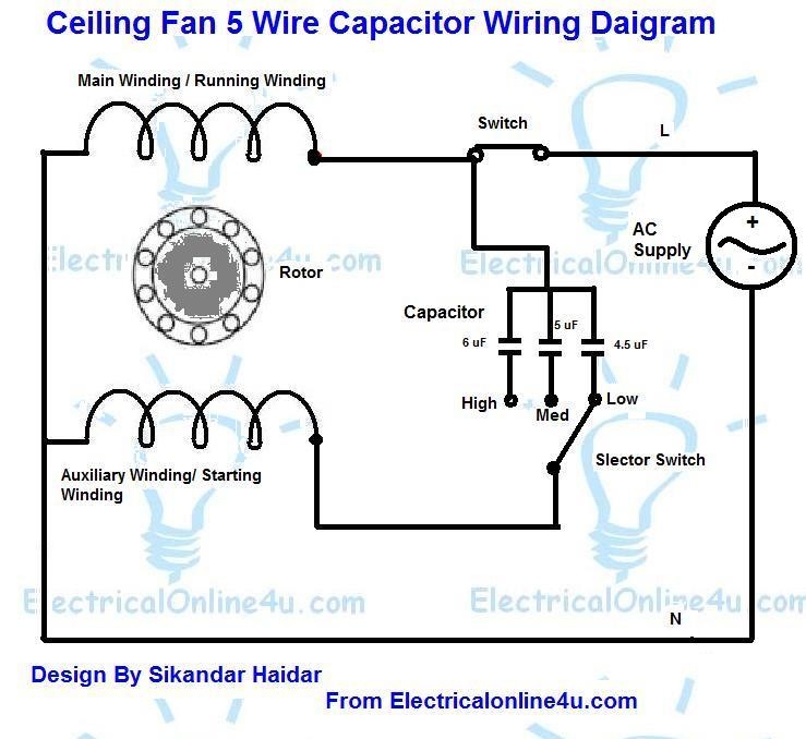
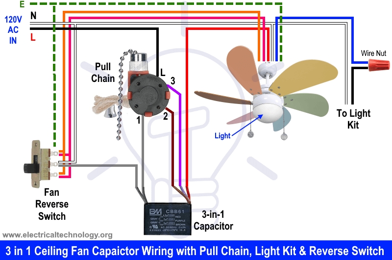
Symbols are electrical representation only. Gm power seat wiring diagram. Ceiling fan capacitor connection diagram 3 wire ceiling fan capacitor diagram 5 wire ceiling fan capacitor diagram and installation role of capacitor in fan and single phase motor so in above diagram the speed switch contacts on l 3 and 2 5 uf and.
+ items in search results. 2 circuit diagram of power factor improvement and controller scientific. Step by tutorial for building capacitor bank and reactive power compensation panel eep.
5 Wire Ceiling Fan Capacitor Wiring Diagram Cadician's Blog
1ph Run Capacitor Wiring Diagram


Single Phase Motor Wiring Diagram With Capacitor Start — UNTPIKAPPS
power factor capacitor bank connection diagram,how to connect three phase power factor capacitor
Ceiling Fan Wiring Diagram With Capacitor Cadician's Blog

Pin on Electrical

Ceiling Fan Capacitor Wiring Wiring Forums
Wiring Diagram Ac Capacitor Home Wiring Diagram

wiring (yet another) Ceiling fan capacitor identification and replacement Home Improvement
☑ How To Connect Capacitor To Fan Motor

Images Of Ceiling Fan Capacitor Wiring Diagram Hunter Simple Capacitor Wiring Diagram

Start Run Capacitor Wiring Diagram And Kwikpik Me Motor Circuit 1440 Best Of Starting มอเตอร์
8 Images Installing 5 Wire Ceiling Fan Capacitor And Description Alqu Blog
8 Images Installing 5 Wire Ceiling Fan Capacitor And Description Alqu Blog
Single Phase Motor Wiring Diagram With Capacitor Start Wiring Diagram
Images Of Ceiling Fan Capacitor Wiring Diagram Hunter Simple Capacitor Wiring Diagram

Ceiling Fan Capacitor Wiring Diagram Wiring Diagram Ceiling fan switch, Ceiling fan wiring

Starting Capacitor Wiring Diagram With Single Phase Motor Start At

Air Conditioner Capacitor Wiring Diagram Wiring Forums